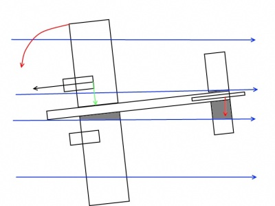
Let’s look picture carefully. The turning moment will be less than fewer arms in case one engine stops. Therefore install engines closest position to fuselage if you can. The clearance 5 mm between prop and fuselage should be enough.
In this article I describe how design features models influence to the model in normal and emergency modes. This will allow you to estimate behavior of model on design stage even.
The main otherness from single engine model is low or zero effectiveness on slow speed. (Only three engine model has some effectiveness due air flow from fuselage engine to fin). It is noticeably in start of running especially. The fin will be in stall earlier other controls.
Twin fin is in the area of blow from rotating propellers. It effectiveness is the same as single engine model. The fins are installed on the ends of stabilizator. It means that stab should have enough strength to hold pressure from fins. The strength is additional weight of the stab. It will necessary to add a lot of weight in the nose to compensate this additional weight on tail.
Plus – this type of landing gear helps to run strait when effectiveness of fin is low.
Minus – if model doesn’t have engine in nose you will have to install additional strong and heavy frame to hold nose landing gear. The third nose strut and wheel also give additional weight.
Plus – It’s lightest construction. The nose of fuselage can be made light. The undercarriage consists from two struts only.
Minus – The tail will lift as you move throttle stick ahead and model will out of course control before gaining speed. It is simple and elegant exit from this bad situation. It is enough to make small camber and convergence of wheels as model will run strait enough.
Summary – Don’t select model with which you will not control on running stage already. If you can handle single engine model during takeoff you’ll control two or multi engines models also with the same result.

|
Let’s look picture carefully. The turning moment will be less than fewer arms in case one engine stops. Therefore install engines closest position to fuselage if you can. The clearance 5 mm between prop and fuselage should be enough. |
|
|
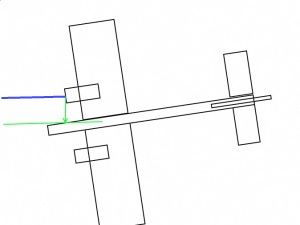
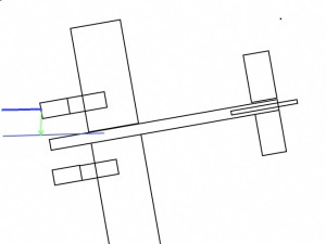
On the pictures you can see two models with different length of nacelles. You can see than in normal mode no differences. Let’s look that will be happen one engine out. Model start to turn to died side. Let’s place the forces and arms. The arm of turning force on model with longer nacelles is less than with short ones. Its means that model will need fewer forces to hold strait path in case of long nacelles. Such model will fly better with one engine out.
Two opposite variants are available.
Ailerons are in the flow from propellers or not.
The central area of wing is under stress from working engines otherwise from single engine model. Due this it should have additional strength to resist it. It refers to the spars, wing sheeting. The wing should be sheeted including area of nacelles.
The ribs holding nacelles must be made from plywood.
The nacelles have to be designed as nose part of single engine model’s fuselage.
Usually twin model kits and ARF have firewalls directed to wingtips. Left one is to portside right one is to starboard side.
Some modelers think that it is done for better single engine fly. They think that thrust lines are directed outside of model and thrust lines match with the engine’s direction. In case of one engine out thrust line directed to outside will help to hold model in the air.
Let’s look this situation carefully.
The thrust lines will be the first.
When we will understand how thrust direction affects on model we review the engine’s angels.
|
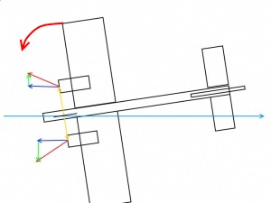
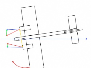
Thrust line (pink) directs outside to wingtips. It consists from couple arms blue one points straight ahead and green one straight sideways. An example if any force turn model to the portside (see scratch) the sum of vectors will try to increase this turn. Our model will be unstable dynamically. Of course than model has speed and fin does his job the model will fly strait. But then model will slow you can have problem with hold model on strait path. You will able to have such problem then model start running especially with tail wheel. |
|
Let’s rotate thrust line inside to the fuselage. If any unwanted forces turn model to portside (see scratch) the sum force generated by thrust lines will try to return model on course. The same thing will be if model turns to the starboard. The model will be steady. |
The thrust will not affect on the model if it is parallel to the axis of the model. In this case the steady and unsteady forces will not appear. I think it is most right design.
How we know how direction of thrust lines effect on fly of model.
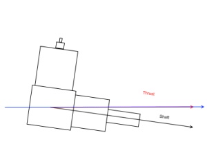
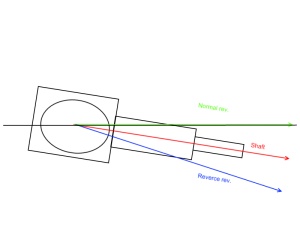
If direction of thrust line matches to the direction of engine’s shaft we will not have problems. Really direction of thrust from rotating propeller doesn’t match with direction engine’s shaft. Due reactive momentum the thrust direct is up and side. The direction of side's shift depends on direction of revolution. Normal revolution is to the left, reverse revolution is to the right. According this we have to point engine’s shaft 3-5 grad. down and side to compensate this torque.
|
Engine is installed straight. Thrust line is pointed up. |
Engine is installed to compensate upper thrust line. |

|
|
| Side shifting thrust lines. | Engine normal revolution is installed right. | Engine reverse revolution is installed right. |

|
|

|
For example: You buy ARF or are building kit or are scratching and see that starboard engine’s shaft is pointed to right and portside one to the left. In this case you have to install starboard engine normal revolution and portside one reverse revolution to obtain thrust straight ahead. If you install portside engine normal revolution you will obtain portside thrust 6 grad. You should modify firewall or motor mount to turn engine’s shaft to right if you want to use engine normal revolution to obtain thrust straight ahead.
I hope that information from this article will help you design your own twin – multiengine project or will predict behave already made model.